CDL1F50-850F: Locking Cylinder, Precise Positioning! The Safety Guardian for Industrial Automation
2025-12-25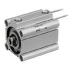
CDL1F50-850F is a cylinder with a locking function produced by SMC, belonging to the CDL1 series. This cylinder adopts a spring lock mechanism to achieve reliable locking in the piston extension direction, making it particularly suitable for industrial automation applications requiring mid-stroke stops, emergency stops, or fall prevention.Core Product Advantages
- Reliable Locking Function Employs a spring lock mechanism to achieve bidirectional locking in the piston extension direction. This ensures the load does not move unexpectedly due to its own weight or external force in the event of air supply interruption or system failure, safeguarding both equipment and personnel.
- Built-in Magnetic Reed Design Comes standard with a built-in magnetic reed, allowing for direct installation of magnetic switches to enable position detection and stroke control, facilitating automated closed-loop control.
- Compact Structural Design Features an aluminum cylinder tube structure, offering light weight, small size, and a compact installation footprint, making it especially suitable for automated equipment with space constraints.
- High Reliability Utilizes high-quality seals and wear-resistant materials, resulting in a long service life and extended maintenance cycles, thereby reducing equipment maintenance costs.
Technical Parameters
| Parameter | Specification | Description |
|---|---|---|
| Bore Size | 50 mm | Medium thrust output |
| Stroke | 850 mm | Long stroke configuration |
| Actuation Type | Double-acting | Bidirectional drive |
| Operating Fluid | Air | Compressed air drive |
| Operating Pressure Range | 0.1 ~ 0.8 MPa | Standard working pressure |
| Proof Pressure | 1.2 MPa | Safety pressure capability |
| Ambient Temperature | -10℃ ~ 60℃ | Operating temperature range |
| Locking Direction | F (Locks in piston extension direction) | Bidirectional locking function |
| Cushioning | Air Cushion | Standard cushioning |
| Port Size | M5×0.8 | Standard port specification |
| Built-in Magnetic Reed | Standard | Supports magnetic switch installation |
Theoretical Thrust Calculation:
- Piston Area: A = π×(50/2)² ≈ 1963.5 mm²
- Theoretical Thrust at 0.4 MPa: F = 0.4 × 1963.5 ≈ 785.4 N
- Theoretical Thrust at 0.6 MPa: F = 0.6 × 1963.5 ≈ 1178.1 N
- Theoretical Thrust at 0.8 MPa: F = 0.8 × 1963.5 ≈ 1570.8 N
Typical Application Scenarios
- Vertical Lifting Equipment In vertical lifting mechanisms, the locking cylinder prevents accidental load descent during air supply interruption, ensuring equipment safety. Applicable in automated warehousing, material handling, etc.
- Robotic Arm Positioning In robotic end-effectors, the locking cylinder enables precise positioning and holding, preventing workpieces from loosening or falling during handling.
- Fixture Clamping In welding fixtures, assembly fixtures, etc., the locking cylinder provides stable clamping force, ensuring workpieces do not shift during processing, thereby improving machining accuracy.
- Safety Guarding Devices In equipment safety doors, protective covers, etc., the locking cylinder can engage quickly in emergencies, preventing injury from operator error.
- Automated Production Lines At stations for positioning, sorting, palletizing, etc., on automated production lines, the locking cylinder ensures accurate workpiece positioning during transfer, enhancing production efficiency.
Product Features
- Locking Mechanism Principle: Uses a spring lock mechanism. When air supply pressure drops below the set value, the lock automatically engages, securing the piston rod in its current position. When air pressure is restored, the lock automatically disengages, allowing normal cylinder operation.
- Mounting Options: Offers various mounting styles (e.g., rod-end flange, double clevis) for flexible integration based on equipment structure.
- Cushioning Configuration: Equipped with an air cushion device that effectively absorbs impact force at the stroke ends, protecting the cylinder and load, and extending service life.
- Magnetic Switch Compatibility: Allows direct installation of small magnetic switches for position detection and stroke control, enhancing equipment intelligence.
Usage Precautions
- Air Quality: Use clean, dry compressed air. Installing filters and oil mist separators at the air supply inlet is recommended to ensure air purity.
- Installation Requirements: Ensure the mounting surface is flat during installation to prevent premature seal damage. In dusty, wet, or oily environments, a bellows boot should be used on the rod side.
- Locking Function Verification: Periodically check that the locking function operates correctly, ensuring reliable engagement during air supply failure.
- Speed Control: Use speed controllers with meter-out flow control to avoid impact damage from excessive speed.
- Regular Maintenance: Regularly inspect seals and clean air lines to ensure long-term, stable cylinder operation.
ConclusionThe CDL1F50-850F Locking Cylinder is the “safety guardian” in the field of industrial automation. It perfectly combines reliable locking functionality, long stroke design, and a compact structure, providing an efficient, reliable, and safe solution for various applications requiring secure positioning and protection against unintended movement.Choosing the CDL1F50-850F means opting for high reliability and high safety to drive your automation system towards greater efficiency!
| CDLQA63-50DCM-F |
| CDLM2B20TN-300-D |
| CDLQL25-40D-B-M9P |
| CDLQA40-50DCM-B |
| CDLQB63-75D-F-M9B |
| CDLQB80-75DCM-B |
| CDLQB40-20D-F-M9P |
| CDLQA32-25D-F |
| CDL1D63-150F-A54 |
| CDLSF125-800-D |
| CDLQB50TF-15DCM-B |
| CDLM2F25-150-E-M9BL |
| CDLSG180-650 |
| CDL1F50-750F-M9BLS |
| CDLQA32-100DCM-F-A93VL |
| CDLQA50-50DC-B |
| CDLJ2B16-100-D |
| CDLQB63-75DM-B |
| CDLSF125-300-Y7BWSDPC |
| CDLQB25-10DM-B-M9B |
| CDLQD50-100DM-F-M9PZ |
| CDLA2B63-350-D |
| CDLQB25-25DM-B |
| CDLQA40-50D-B-XC35 |
| CDLQB50-10D-F |